




Precision in Motion: The Definitive Guide to Selecting Rack and Pinion Systems for High-Performance Applications

Sponsored by GAM
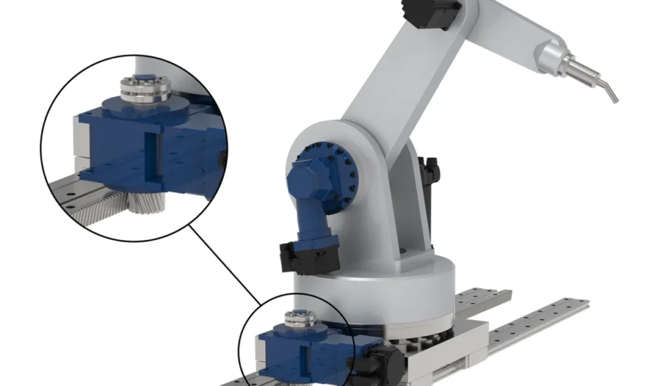
In the world of industrial automation, where fractions of a millimeter can determine the success or failure of a manufacturing process, the selection of the drivetrain is paramount. Among the various mechanisms available to engineers, the rack and pinion system remains a foundational technology for converting rotary motion into linear travel. From the simple mechanics of a manual scissor jack to the complex, high-speed 7th-axis integration of an articulated robot, the rack and pinion is the silent workhorse of modern motion control.
However, selecting the "right" system is far from a trivial task. It is a balancing act of physics, material science, and economic strategy. Choosing an undersized component invites catastrophic mechanical failure, while over-engineering leads to inflated costs and unnecessary spatial footprints. To navigate these complexities, engineers must understand the interplay between feed force, velocity, inertia matching, and tooth geometry.
The Fundamentals: How Rack and Pinion Systems Define Motion
At its core, a rack and pinion system is elegantly simple. The "pinion" acts as the rotary input, typically driven by a servo gearbox, while the "rack" serves as the linear component, featuring precision-cut teeth that engage with the pinion. Depending on the specific application requirements, the system can be configured in two primary ways: the pinion travels along a fixed rack, or the rack itself moves while the pinion remains anchored.
While the concept is intuitive, the execution requires high-precision engineering. "If you go too small with your rack and pinion, it can break," explains Matt Ruggles, senior design engineer at GAM, a leading U.S.-based manufacturer of servo gear reducers and motion control components. "If you go too large, you might run into space constraints, and you’ll be paying for more rack and pinion than you need."
Chronology of the Selection Process
Designing a motion system is rarely a linear path; rather, it is an iterative loop that begins with the identification of primary performance drivers. For most engineers, the process follows a logical sequence:
1. Defining the Primary Constraint (Force vs. Speed)
The initial phase of the design process focuses on whether the application prioritizes raw feed force or rapid travel speed. When feed force is the priority, the engineering focus shifts to the structural integrity of the rack teeth and the torque capacity of the pinion-gearbox interface. Conversely, when speed is the priority, the pinion diameter and the gear ratio are optimized to achieve the target velocity with the available motor input.
2. Matching the Motor and Load
Once the force and speed requirements are established, the focus shifts to inertia matching. A well-designed system ensures that the inertia of the load, reflected back through the gearbox to the motor, is within an acceptable ratio. This balance is critical for the stability of the control loop; a poorly matched system will exhibit vibrations, overshoot, or sluggish response times.
3. Precision Requirements and Tooth Geometry
As the design matures, engineers must select the specific tooth quality and configuration. The selection of straight versus helical teeth is a pivotal decision. Helical teeth, which are cut at an angle, allow for progressive engagement. This results in significantly quieter operation and higher power density. However, they introduce an axial load component that must be accounted for in the bearing design. Straight teeth are simpler and more cost-effective but engage simultaneously, leading to higher noise levels and potential vibrations at high speeds.
Supporting Data: The Impact of Pinion Sizing
The size of the pinion is arguably the most influential variable in system performance. The relationship between the pinion and the rack determines the system’s "mechanical leverage."
The Small Pinion Advantage
For high-precision applications, smaller pinions are generally preferred. A smaller pinion reduces the effect of backlash or rotational error on the linear position. If a gearbox has a small amount of "lost motion," that error is magnified by the radius of the pinion. Therefore, a smaller radius effectively "filters out" the mechanical noise, resulting in tighter linear accuracy. Furthermore, smaller pinions require less torque from the motor to achieve a specific feed force, allowing for the use of more compact, efficient, and cost-effective motor-gearbox combinations.

The Large Pinion Trade-off
Larger pinions are utilized when high travel speeds are required. Because a larger pinion covers more linear distance with every rotation, the system can achieve higher speeds without pushing the motor to its RPM limits. However, this comes at the expense of force multiplication and increased sensitivity to system backlash.
Engineering Perspectives: Expert Insights from GAM
The complexity of these variables is why expert consultation is often required. Matt Ruggles notes that a common mistake in the industry is the "siloed" approach to design.
"One consistent mistake I see is engineers sizing the system around only one variable—feed force, for example—and not accounting for others until it’s too late," Ruggles says. "All of a sudden, they realize they need to go up a rack size, which forces them to get a bigger gearbox, and suddenly everything has doubled in cost."
This phenomenon, known as "cascading design changes," can derail project timelines and budgets. When an engineer discovers that a chosen gear ratio results in an inertia mismatch, they may be forced to change the gearbox ratio. This adjustment, in turn, reduces the output speed, which may then fail to meet the original speed requirements of the machine, forcing the designer back to the start of the process.
Implications for Modern Automation
The integration of 7th-axis systems—where a rack and pinion allows a robotic arm to travel along a long linear track—has pushed the demand for higher-precision rack and pinion systems to new heights. These systems must maintain micron-level repeatability over several meters of travel, often under heavy payloads.
The choice of rack and pinion is also becoming more critical as manufacturers push for higher throughput. In high-speed packaging or automotive assembly, the dynamics of the rack and pinion influence the duty cycle of the machine. A system that is optimized for inertia and rigidity can accelerate faster and settle quicker, directly increasing the output of the production line.
Streamlining the Selection with Specialized Tools
To prevent the pitfalls of manual calculation and iterative errors, manufacturers like GAM offer advanced sizing software. These digital tools allow engineers to input their specific parameters—feed force, moving mass, travel speed, and positional accuracy requirements—and instantly evaluate the impact of different component configurations.
By utilizing these tools, designers can compare the performance of different rack tooth qualities, pinion diameters, and gearbox ratios in real-time. This allows for a "system-level" optimization where the motor, gearbox, and rack are selected as a cohesive unit rather than as disparate parts.
Conclusion
The rack and pinion system remains an indispensable component of mechanical engineering, offering a unique combination of high force, high speed, and long-travel capability. However, its performance is entirely dependent on the rigor of the selection process. By prioritizing inertia matching, understanding the nuances of tooth geometry, and leveraging modern sizing software, engineers can build motion systems that are not only accurate and efficient but also cost-optimized.
As industries move toward greater levels of automation and precision, the importance of these foundational components will only grow. For engineers facing these challenges, the takeaway is clear: don’t look at the rack, the pinion, or the gearbox in isolation. Look at the system as a whole.
To explore how your next motion control project can benefit from optimized rack and pinion integration, visit GAM for technical resources and sizing support.