




The Mechanics of Flow: Understanding Fluid Dynamics in Industrial Piping Systems

By Mike Sondalini, PWW EAM System Consultant
With permission from the BIN95 Business Industrial Network
In the vast architecture of modern industrial facilities, the movement of fluids—whether liquids or gases—serves as the lifeblood of production. From cooling water in power plants to complex chemical feedstocks in refineries, these substances must be transported from storage to the point of use with precision and efficiency. However, the movement of fluids through pipes is not merely a matter of pumping; it is a complex interaction of physics, fluid properties, and mechanical design. Mastering these principles is essential for minimizing pressure loss, extending equipment lifespan, and optimizing process performance.

The Fundamentals of Pipe Wall Interaction
To understand how a system performs, one must first look at the interface between the fluid and the conduit. Every fluid flowing through a pipe makes direct contact with the interior pipe wall. Crucially, no pipe is perfectly smooth; the wall possesses inherent surface roughness, measured by the height of microscopic projections that jut into the flow path.
The Physics of Shear
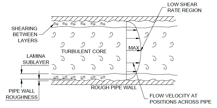
As fluid moves, these projections create a "drag" effect. In the valleys between these projections, fluid velocity is significantly impeded, moving at a near-standstill. As we move away from the wall toward the center of the pipe, the velocity increases. This gradient creates shear—a tearing force between layers of fluid.
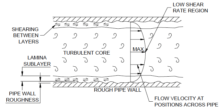
The shear rate is highest at the pipe wall (where velocity is effectively zero) and lowest at the center, where the fluid core moves at its maximum velocity. Consequently, the central core of the fluid is the first to exit the pipe, a phenomenon that engineers must account for when managing process timing and chemical dosing.
Friction, Laminar Flow, and Turbulent Dynamics
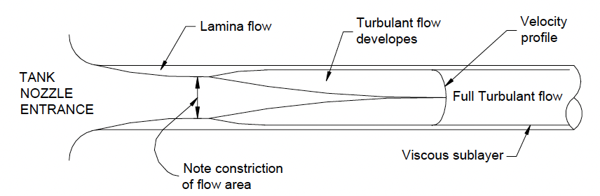
The energy lost in a piping system is largely a result of friction. This friction gives rise to two distinct regions of flow: the laminar sublayer and the turbulent core.
The Laminar Sublayer
Because of wall-induced friction, a thin layer of slow-moving fluid persists along the inner surface of the pipe. This is known as the laminar sublayer. Its thickness is dynamic, ranging from tenths of a millimeter to several millimeters, depending on flow speed, wall roughness, and the fluid’s specific viscosity.
In low-velocity "laminar" flow, this layer is stable. However, in high-velocity "turbulent" flow, the sublayer acts as a boundary. Beyond this boundary, the flow is chaotic, characterized by eddies and vortices that tumble randomly. This is a region where "confused lumps" of fluid move through the system, causing the energy dissipation that engineers strive to minimize.

The Influence of Viscosity and Density
Not all fluids obey the same rules of motion. Industrial engineers categorize these substances into two primary groups based on their reaction to shear:
- Newtonian Fluids: Substances like water or gasoline, where the shear rate remains constant regardless of velocity changes.
- Non-Newtonian Fluids: Complex substances like blood, paint, or polymer slurries, where the shear rate changes as velocity changes.
Viscosity as a Design Variable
Viscosity represents a fluid’s resistance to flow—or its "slipperiness." High-viscosity fluids are inherently harder to shear, which results in a thicker laminar sublayer and higher energy requirements for transport. Furthermore, fluid density plays a critical role; denser fluids possess more mass per unit volume, requiring more work to initiate and maintain movement.

Temperature also acts as a primary lever in fluid dynamics. Generally, as temperature rises, the viscosity and density of liquids decrease, which can reduce the energy required to move them. Designing a system without accounting for temperature-induced viscosity shifts is a common cause of pump cavitation and process failure.
Velocity Effects and Pressure Loss
The relationship between velocity and pressure is perhaps the most critical factor in industrial piping design. Experiments have consistently demonstrated that:
- In Laminar Flow: Pressure loss is directly proportional to velocity ($P propto V$).
- In Turbulent Flow: Pressure loss is proportional to the square of the velocity ($P propto V^2$).
The "Smooth" vs. "Rough" Paradox
An intriguing aspect of pipe design is that the "roughness" of a pipe is relative to the velocity of the fluid. At low speeds, the laminar sublayer is thick enough to cover the roughness projections of the pipe wall, effectively making the wall "smooth." As velocity increases, the turbulent eddies penetrate the sublayer, exposing those roughness peaks. Once the peaks poke through the sublayer, the pipe wall is considered "rough," and friction losses escalate dramatically.
Designers must therefore perform a delicate balancing act. While larger pipe diameters reduce energy loss by decreasing velocity, they significantly increase initial capital expenditure (CAPEX) for installation. Finding the "sweet spot" between operational efficiency and material cost is the hallmark of effective industrial engineering.
Minor Losses: The Impact of Fittings
While the straight pipe run is the primary contributor to friction, fittings such as elbows, bends, reducers, and tees are the "hidden" thieves of pressure.
Every time a fluid is forced to change direction or diameter, the flow profile is disrupted, creating new, twisting eddies. These eddies interfere with the laminar flow pattern, resulting in "minor" losses that, when aggregated, can significantly degrade system performance. Best-practice design dictates that changes in direction or diameter should be as gradual as possible to minimize the downstream "eddy wake" that plagues poorly designed piping configurations.
The Unique Challenge of Gas Flow
Gases present a distinct set of challenges because they are compressible. Unlike liquids, which maintain a relatively constant density, the density of a gas is inextricably linked to its pressure.
The Expansion Principle
As a gas flows through a pipe, frictional losses lead to a gradual drop in pressure. Because the gas is at a lower pressure, its density decreases. To maintain a consistent mass flow rate, a gas that is expanding as it travels must increase its velocity. Consequently, gas flows faster at the end of a pipe than it does at the start.
This expansion has thermodynamic consequences: expanding gas cools. This is the fundamental principle behind refrigeration and air conditioning. In industrial settings, this cooling effect is why compressed air lines are often cold to the touch and why water vapor frequently condenses within pneumatic valve actuators, leading to potential corrosion or equipment malfunction.
Implications for Industrial Reliability
The implications of these fluid dynamic principles for plant reliability are profound. If a system is not designed to account for the interplay between fluid velocity, viscosity, and component configuration, the facility will suffer from:
- Increased Energy Consumption: Overworking pumps to compensate for unnecessary pressure drops.
- Equipment Fatigue: The presence of turbulent eddies can cause vibration and cavitation, leading to premature failure of seals, bearings, and impellers.
- Process Inefficiency: Incorrectly calculating flow regimes can lead to off-spec product quality if residence times or flow patterns do not match design specifications.
The Path Forward
For those involved in Asset Management and Reliability, the lesson is clear: fluid dynamics is not just a theoretical academic subject; it is a practical tool for operational excellence. Whether one is selecting a pump, designing a distribution header, or troubleshooting a pneumatic control valve, an understanding of the laminar sublayer, the Reynolds number, and the compressible nature of gases is essential.
By optimizing piping geometry and maintaining a keen eye on fluid properties, maintenance teams can shift from reactive repair cycles to a state of predictive, high-performance reliability. As industrial systems continue to evolve in complexity, those who master the "invisible" behavior of fluids within their pipes will remain at the forefront of operational success.